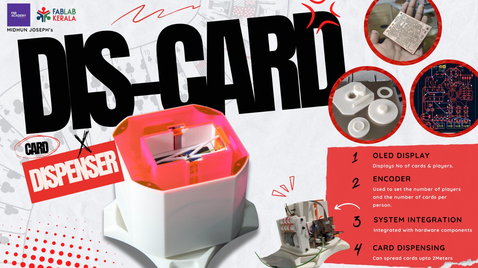
DIS-CARD
The primary function of the DIS-CARD project is to distribute playing cards among players for various card games such as UNO, poker, etc. The device accepts input for the number of players and the number of cards per player, and then automatically distributes the cards accordingly.
Although there are existing products on the market, I aim to build a low-cost alternative. The currently available product on Amazon costs around 18,000 INR, but my project will cost only around 4,000 INR.
How it works
- User Input: The user inputs the number of players and cards per player via the user interface.
- Initialization: The system initializes the turntable mechanism and card-throwing mechanism.
-
Card Distribution:
- Turntable Mechanism: The turntable rotates to align with each player.
- Card Throwing Mechanism: The mechanism throws a specified number of cards to each player one at a time.
-
Completion:
The process repeats until all players receive the correct number of cards.
Features of DIS-CARD
-
Automated Card Distribution:
- Automatically distributes playing cards to players based on user input for the number of players and cards per player.
-
User-Friendly Interface:
- Simple interface for users to input the number of players and the number of cards each player should receive.
-
Cost-Effective:
- Designed to be affordable, costing around 4,000 INR compared to similar products on the market costing around 18,000 INR.
-
Customizable:
- Capable of being adapted for different card games by adjusting the settings.
-
Efficient Mechanisms:
- Incorporates a turntable mechanism to rotate and align the distributor with each player.
- Card throwing mechanism designed to distribute cards one at a time accurately.
-
Adaptability:
- Utilizes modified components (e.g., converting a 180-degree servo to a 360-degree servo) to meet design needs with available resources.
-
Easy Assembly and Maintenance:
- Designed with ease of assembly and maintenance in mind, using 3D printed and laser-cut parts.
-
Future Expandability:
- Designed with the potential for future upgrades, such as mobile app integration and enhanced automation features, the addition of the shuffling mechanism
CARD- THROWING MECHANISM
My initial idea for distributing cards among players involved using a DC motor and a servo motor. The DC motor would be connected to a roller to help throw the card, while the servo motor would push one card at a time. With this concept in mind, I began designing the system accordingly.
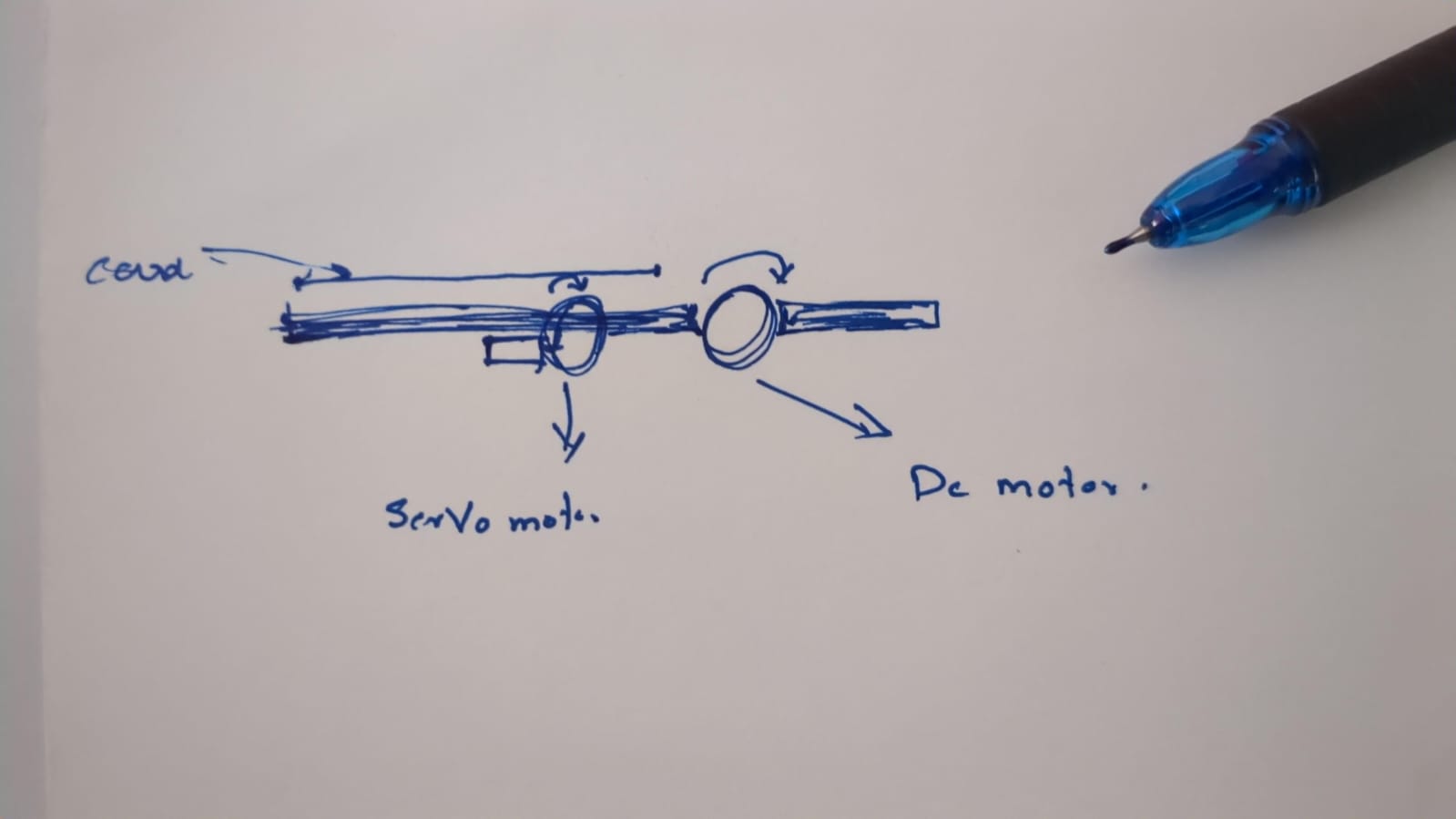
This is the initial design that I have done:
Then I 3D printed the parts, connected the motors, uploaded the sketch to the Arduino, and ran a test. This is how it turned out:
you can see the documentation of the 3d printing week for any reference
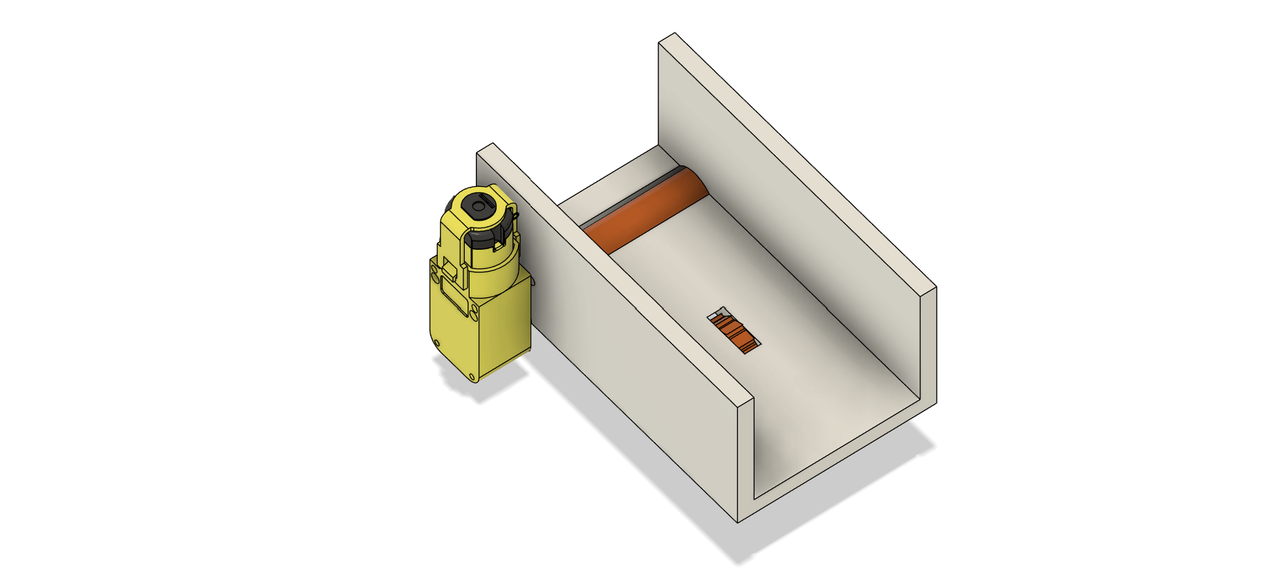
After this, I realized that my initial concept wasn't working well. The card-throwing mechanism attached to the DC motor didn't have enough speed to shoot the card effectively. So, I decided to redesign the entire setup.
Now, I've conceived a new concept involving two rollers meshed together. The idea is that the space between these rollers will provide more powerful propulsion for throwing the cards. Additionally, I upgraded to a 12V DC motor for increased power and efficiency in executing this concept.
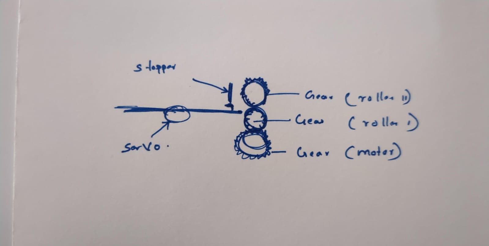
this is the design
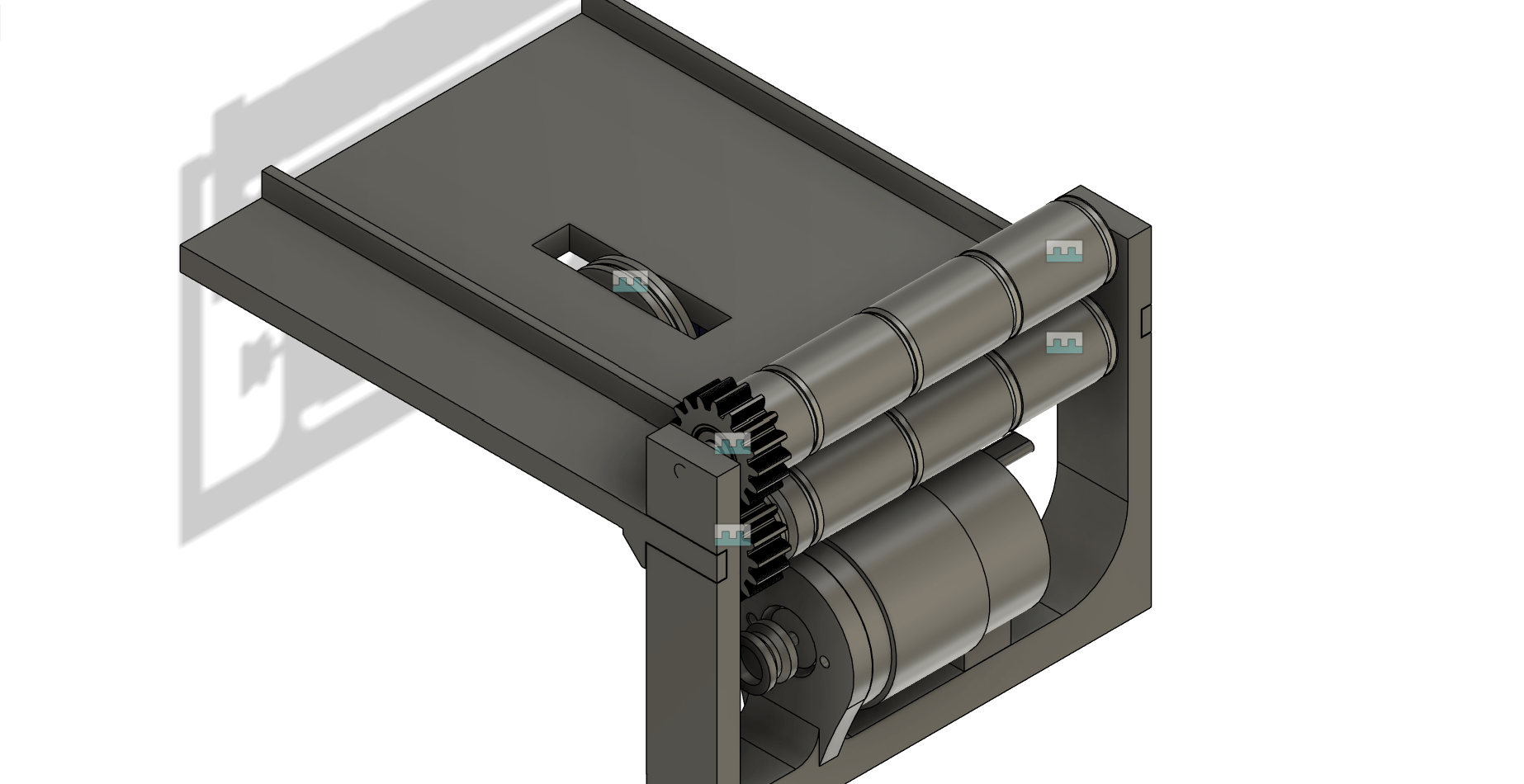
Then I printed the parts assembled them and tested the mechanism
Now the system works just fine but there are things that needed to be figured out
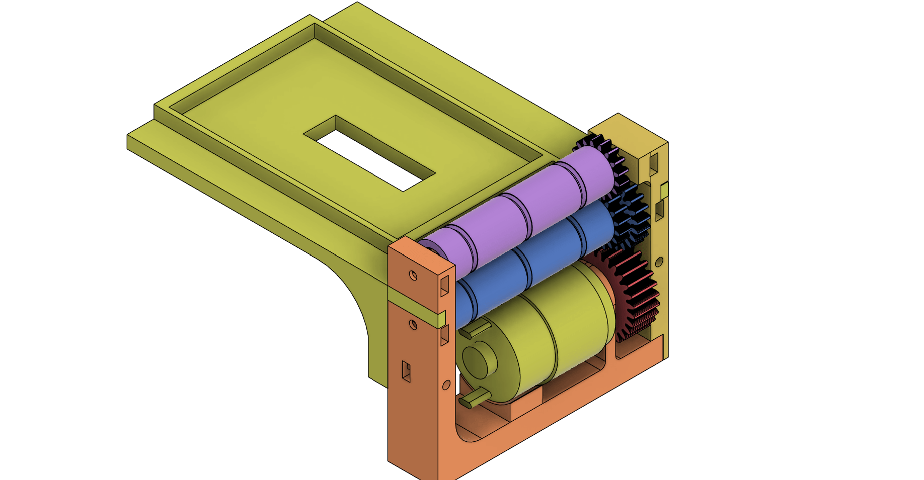
This is the refined version of the card throwing mechanism: the gear heights are reduced and a stopper is added to allow only one card to pass through.
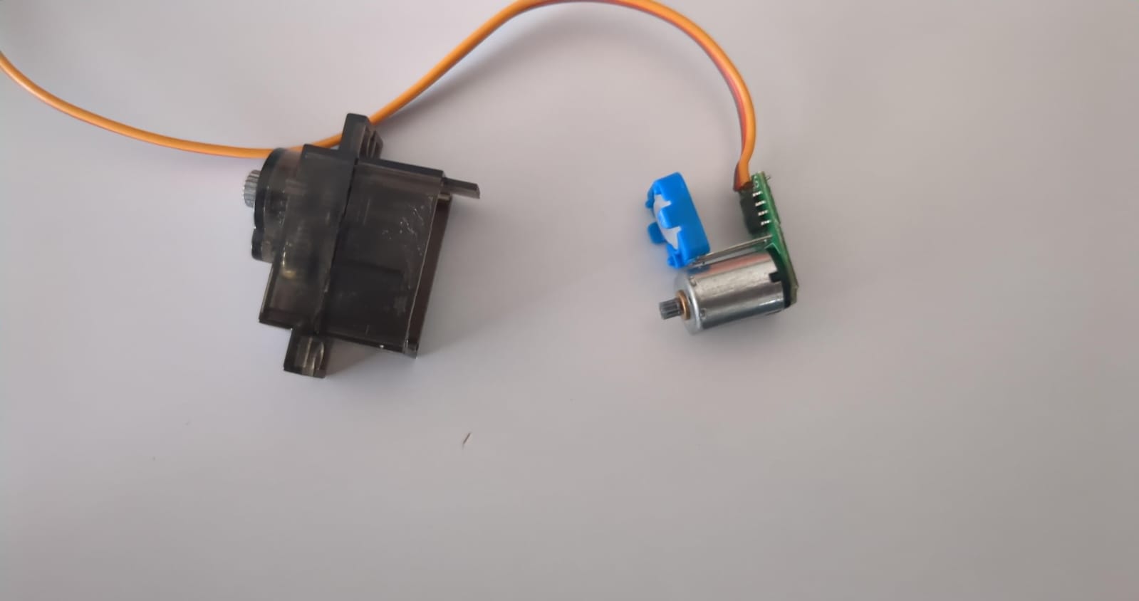
The problem is with my current servo motor—it's a 180-degree servo. I think switching to a 360-degree servo would make it more efficient and potentially faster. I searched locally for a 360-degree servo but couldn't find one. While browsing online, I discovered that a 180-degree servo can be modified into a 360-degree one, so I decided to give it a shot.
Here is how to convert a 180-degree servo to a 360-degree servo
Dismantle the servo
Now, connect the servo to any development board you have assembled. Upload this sketch to the board.
#include <Servo.h>  // Include the Servo library

Servo myservo;      // Create a Servo object

void setup() {
  myservo.attach(9);  // Attach the servo on pin 9 to the Servo object
}

void loop()
{
  // Stop the servo
  myservo.write(90);   // Stop
  delay(3000);         // Pause for 1 second
}
Using a screwdriver, carefully adjust the potentiometer until the motor stops rotating. Once you find this point, secure the potentiometer in place with glue.
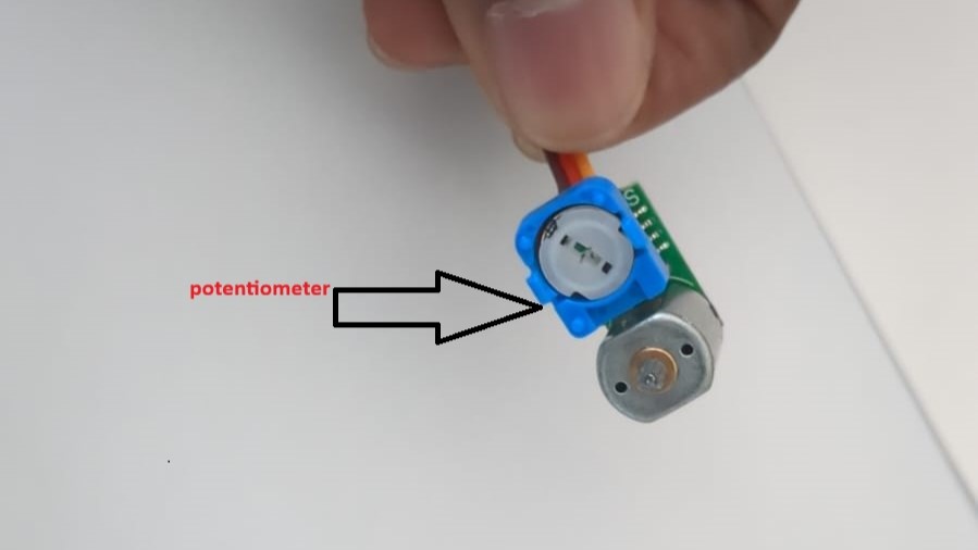
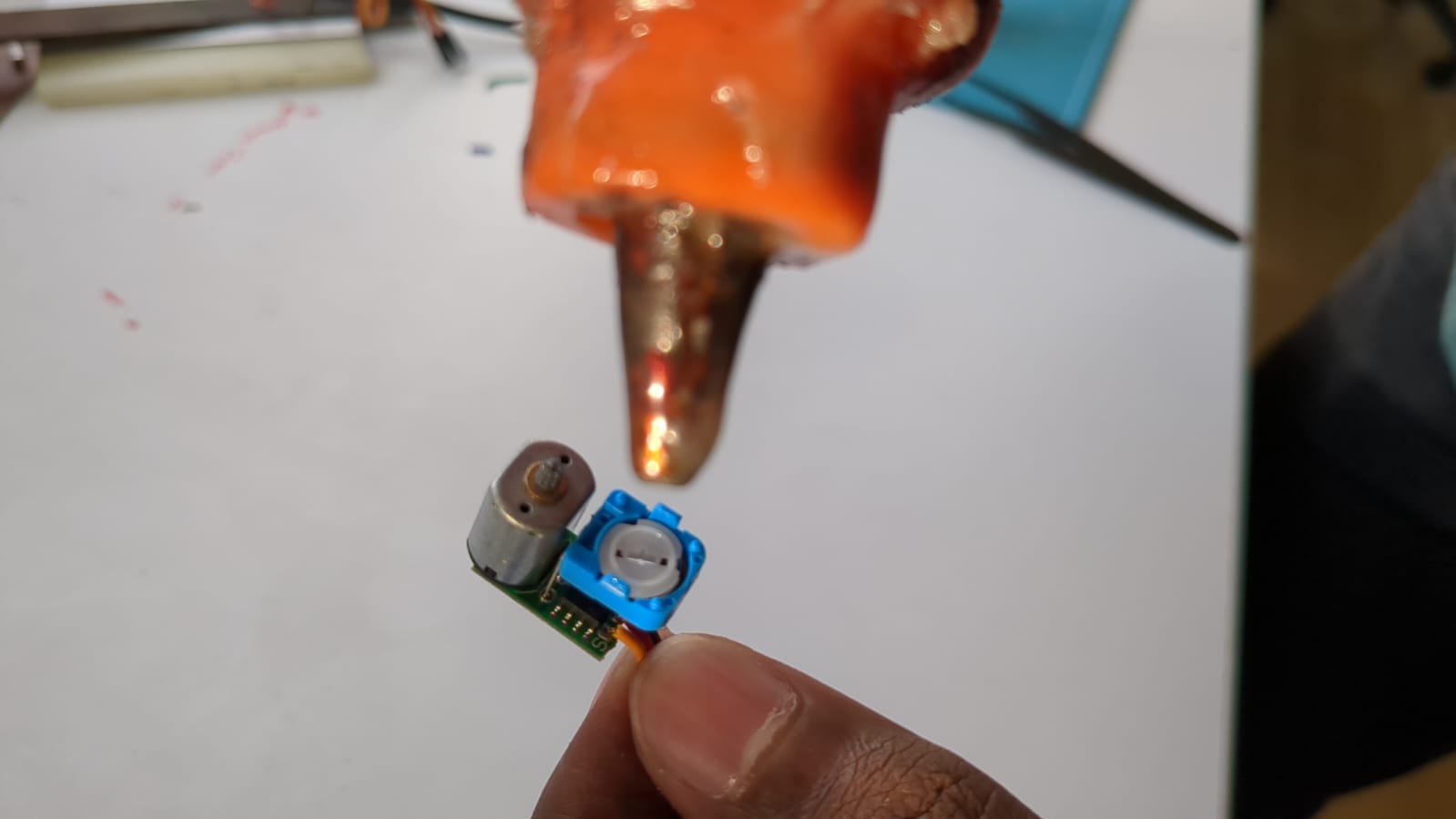
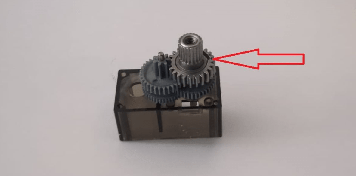
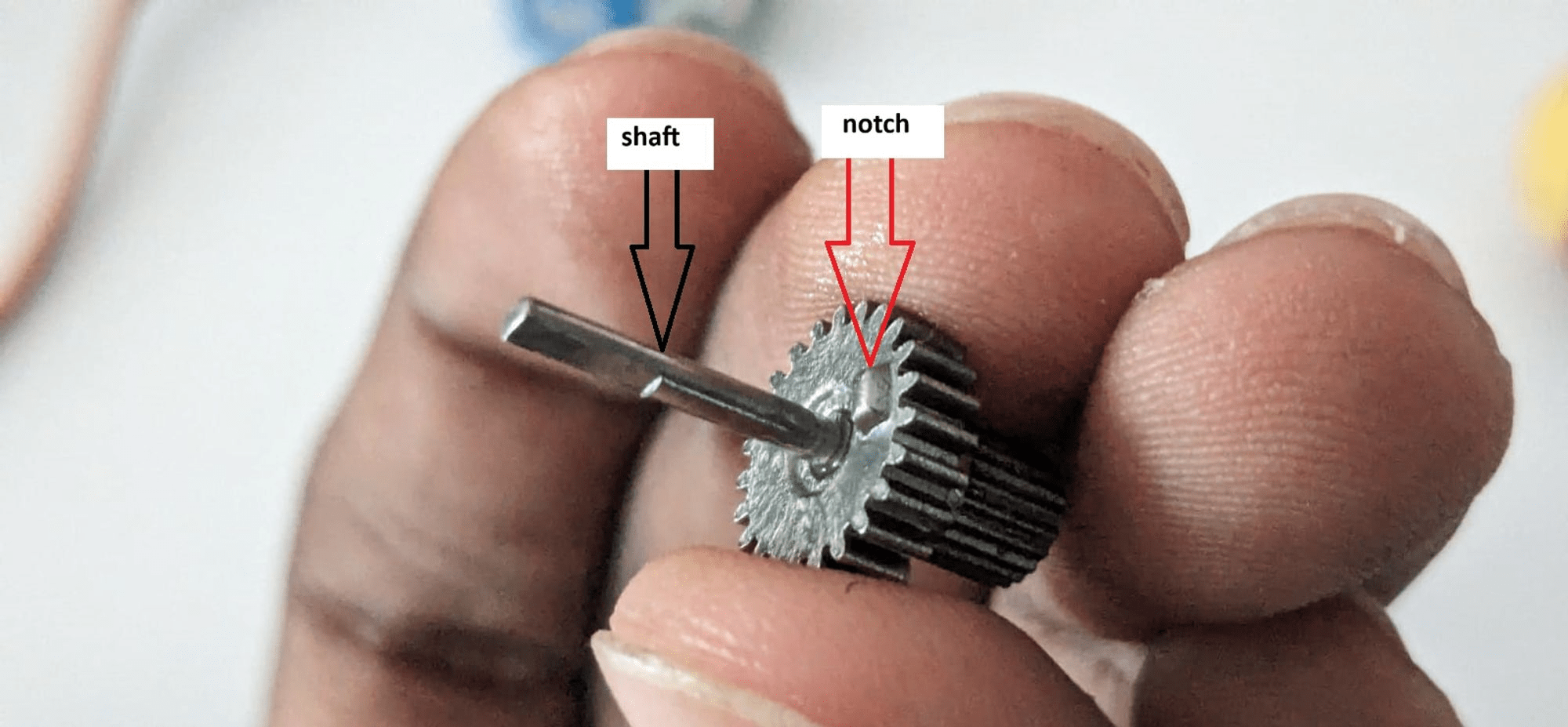
In the gear section, carefully remove the topmost gear. Grind out the notch at the bottom of that gear. Also, inspect the shaft of the gear closely—you'll notice a cut portion where the shaft rotates the potentiometer. Use a grinder or cutter to cut the shaft at this point.
Now, reassemble the motor as it was originally.
Voila! Now we have successfully converted it into a 360-degree servo motor.
Here's a sample sketch to test the servo motor,
#include <Servo.h>  // Include the Servo library

Servo myservo;      // Create a Servo object

void setup() {
  myservo.attach(9);  // Attach the servo on pin 9 to the Servo object
}

void loop() {
myservo.write(180); //clockwise rotation
delay(2000); //rotation duration in ms
myservo.detach(); //detach servo to prevent “creeping” effect
delay(500); //short pause
myservo.attach(9); //reattach servo to pin 9
myservo.write(0); //counterclockwise rotation
delay(2000); //rotation duration in ms
myservo.detach(); //detach servo to prevent “creeping” effect
delay(500); //short pause myservo.attach(9); //reattach servo to pin 9 before looping

}
myservo.write(180); // Full speed clockwise
myservo.write(90); // STOP
myservo.write(0); // Full speed anticlockwise
180 causes your servo to spin clockwise at full speed. 0 causes it to spin counterclockwise at full speed. Values of 45 and 135, for example, have the servo spin slower in their respective directions while 90 theoretically should keep the servo at rest. However, we say “theoretically” because the servo is never really perfectly centered. This causes the servo to creep ever so slowly in one direction or another. Besides being annoying it also ruins the accuracy of your project. So to prevent this creeping, we attach and detach the servo when necessary in the above Arduino code. Detaching it leaves it unpowered and therefore completely at rest.
With the card shooting mechanism nearly operational, I'll now proceed to work on the turntable mechanism.
ROTATING-MECHANISM
In the turntable mechanism, I utilized a stepper motor with a gear ratio of 1:11 for rotating the table. Here is the design of the turntable:
Then I printed the turntable parts and assembled them. Here is how it turned out.
The turntable rotates smoothly without any frictional issues—I'm glad for that!
Then I fixed the stepper motor and, using an Arduino shield, tested the turntable with the motor. Here is a short clip of the testing.
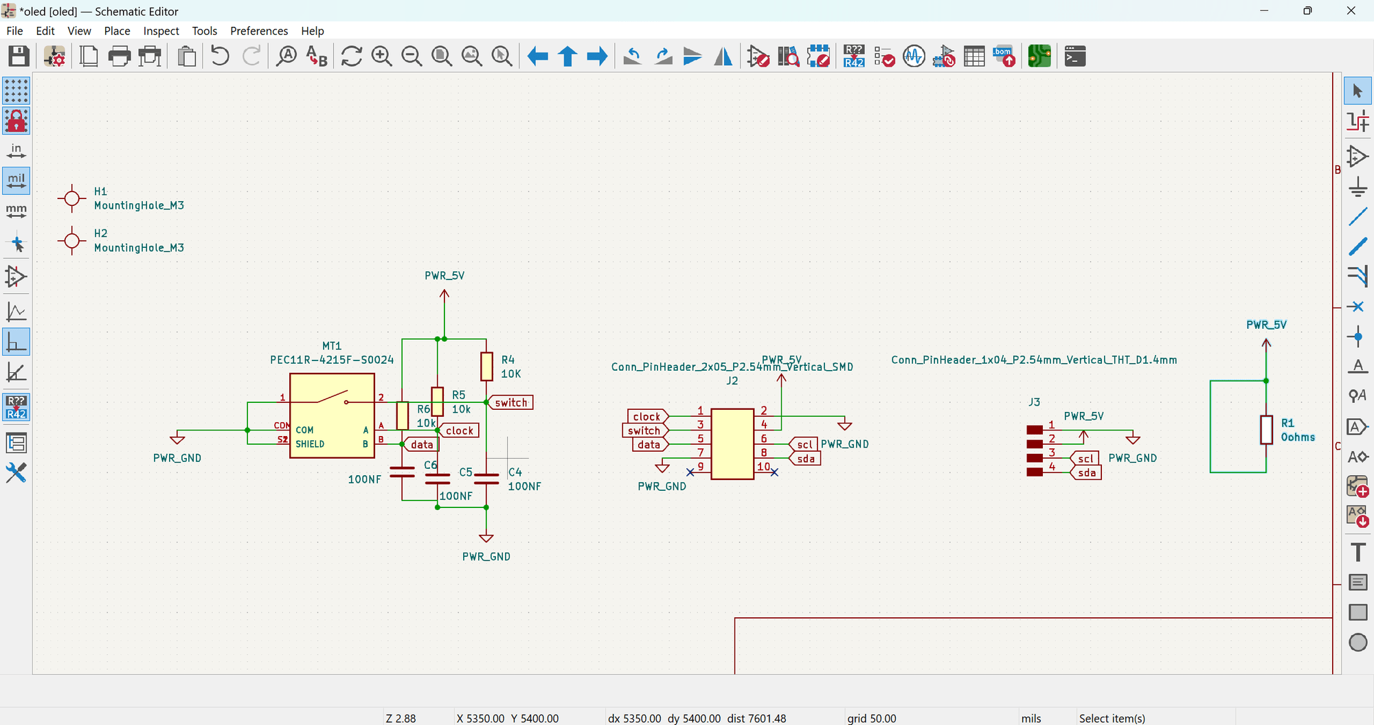
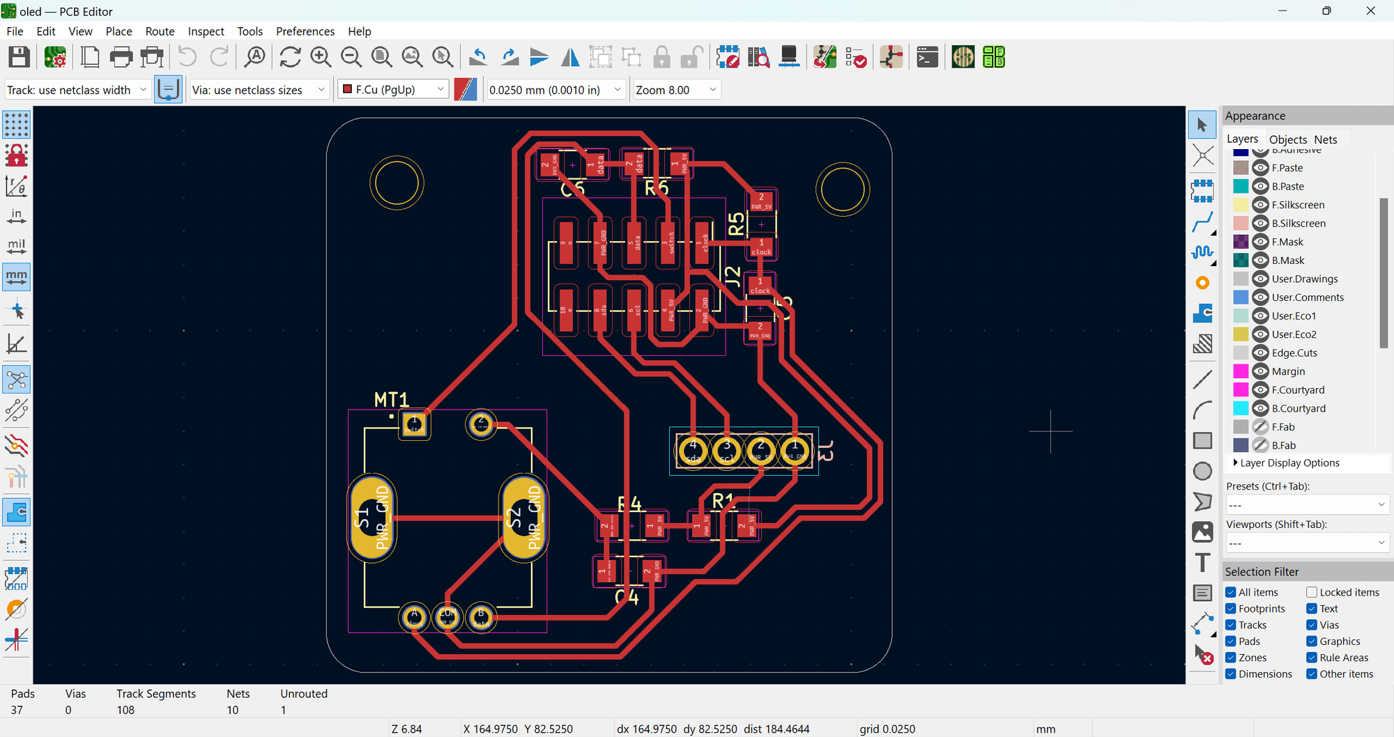
ELECTRONICS AND PROGRAMMING
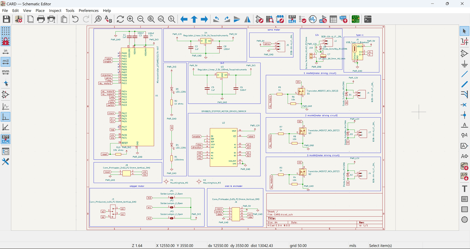
For DIS_CARD, I have two PCB boards: one for the OLED screen and rotary encoder, and another for the main board. I designed these boards using KiCAD. All design files, including Gerber files, are available for download at the bottom of this page.
ELECTRONICS BOM
| SL NO | COMPONENTS | SPECIFICATIONS | QUANTITY | PRICE | TOTAL |
|---|---|---|---|---|---|
| 1 | Micro-controller | SAMD-21-E17A | 1 | ₹350 | ₹350 |
| 2 | Screw-terminal | 2pos | 1 | ₹14 | ₹14 |
| Capacitor | 1uf | 3 | ₹4 | ₹12 | |
| 4 | 100nf | 4 | ₹2 | ₹8 | |
| 5 | 100uf electrolytic SMD | 1 | ₹27 | ₹27 | |
| 6 | Resistor | 100 ohms | 1 | ₹7 | ₹7 |
| 7 | 1 k ohms | 4 | ₹8 | ₹32 | |
| 8 | 10 k ohms | 4 | ₹9 | ₹36 | |
| 9 | Conn- header SMD | 4pos (2x2) | 1 | ₹8 | ₹8 |
| 10 | Conn header SMD | 4pos (1x4) | 1 | ₹4 | ₹4 |
| 11 | Motor driver | DRV8825 | 1 | ₹114 | ₹114 |
| 12 | LED SMD | RED (1206) | 1 | ₹2 | ₹2 |
| 13 | BLUE(1206) | 1 | ₹2 | ₹2 | |
| 14 | Voltage regulator | 3.3 v 100mA LDO | 1 | ₹12 | ₹12 |
| 15 | 5 v 1A LDO | 1 | ₹18 | ₹18 | |
| 16 | Mosfet | N-CH 30v 1.7A SOT-323 | 3 | ₹32 | ₹96 |
| 17 | JST connecter | 1x2 male | 3 | ₹2 | ₹6 |
| 18 | 1x2 female | 3 | ₹2 | ₹6 | |
| 19 | 1x3 male | 1 | ₹3 | ₹3 | |
| 20 | 1x3 female | 1 | ₹3 | ₹3 | |
| 21 | Copper Clad PCB | Double-sided FR4 -(15cm x 10cm) | 1 | ₹250 | ₹250 |
| TOTAL | ₹1010 |
all the electronics components are from the FABLAB inventory
MATERIAL AND MACHINING BOM
| SL:NO | PART NAME | SOURCE | QUNATITY | PRICE | TOTAL |
|---|---|---|---|---|---|
| 1 | DC MOTOR | FABLAB INVENTORY | 1 | ₹38 | ₹38 |
| 2 | SERVO MOTOR | FABLAB INVENTORY | 1 | ₹140 | ₹140 |
| 3 | STEPPER MOTOR | FABLAB INVENTORY | 1 | ₹170 | ₹170 |
| 4 | ROTORY ENCHODER | FABLAB INVENTORY | 1 | ₹40 | ₹40 |
| 5 | OLED SCREEN | FABLAB INVENTORY | 1 | ₹250 | ₹250 |
| 6 | ACRYLIC SHEET | FABLAB INVENTORY | .5 sq ft | ₹200 | ₹100 |
| 7 | 3D PRINTING | FABLAB INVENTORY | 18 hrs | ₹100 | ₹1800 |
| 8 | M3 NUTS AND BOLTS | FABLAB INVENTORY` | 15 | ₹5 | ₹125 |
| 9 | M4 NUTS AND BOLTS | FABLAB INVENTORY | 5 | ₹5 | ₹25 |
| 10 | PCB MILLING | FABLAB INVENTORY | .5hrs | ₹150 | ₹75 |
| 11 | RUBBER BANDS | LOCAL SHOP | 20 | ₹.5 | ₹10 |
| TOTAL | ₹2773 |
so the total amount will be 3783 INR
Main-Board
The main board consists of the SAMD21 processor. It includes a stepper motor driver for the stepper motor, a DC motor driving circuit with MOSFETs , and various other components. The board also features pin headers for connecting the other PCB.
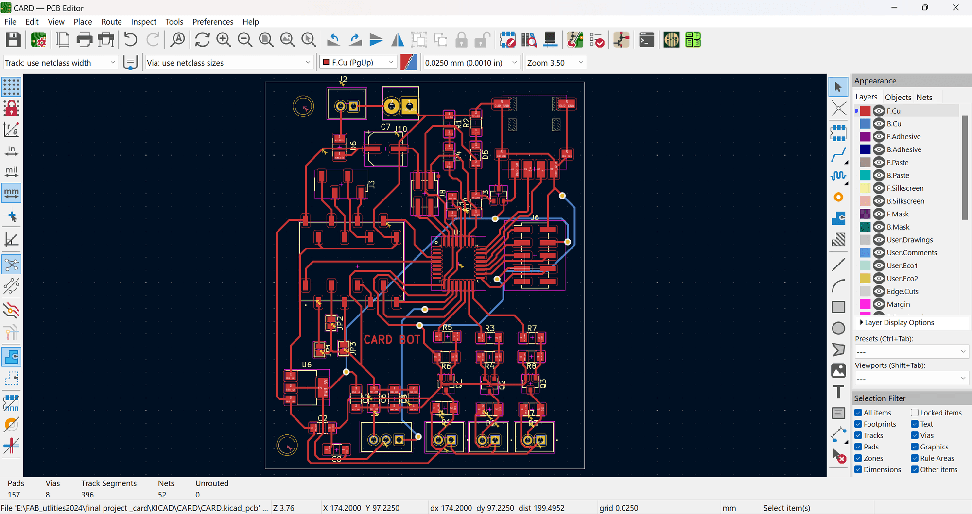
Next, I took the gerber files and converted them into PNG format using a custom tool developed in-house by our developer, Midlaj. You can upload the gerber files and generate the PNGs for milling purposes.
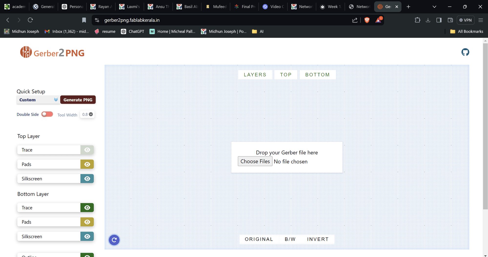
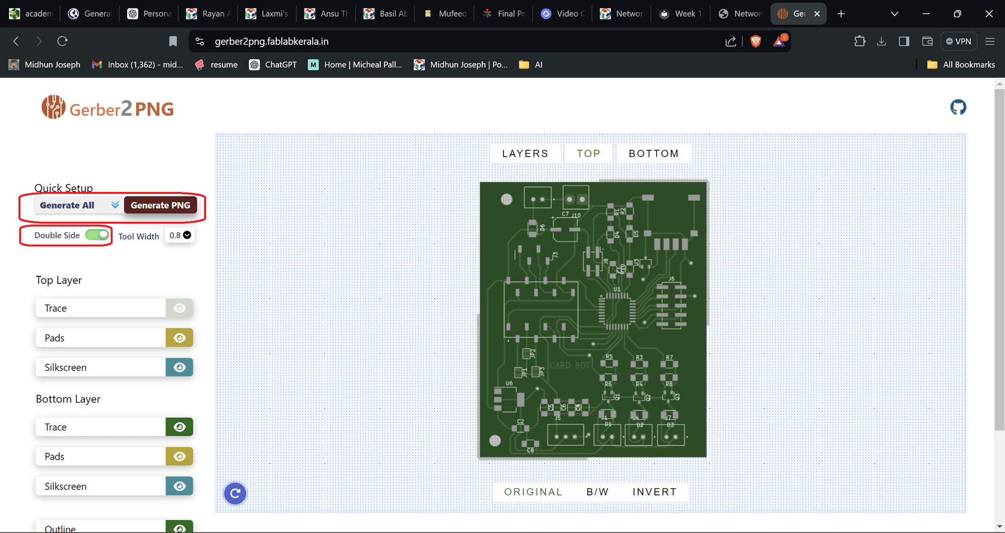
You can download the zip files of the PNG and proceed with milling for detailed documentation, you can check the electronics production week
then i proceed with the soldering phase and completed the pcb
After soldering, I uploaded the basic Blink sketch to check the functionality of the board. Voila, it's working! for detailed documentation, you can check the embedded programming week
2nd PCB
The second PCB consists of the OLED screen and a rotary encoder.
Then, I followed the same procedure as with the other PCB, and here is the result.
Then I proceeded to programming.
Initially, I created a menu setup for the OLED screen. Here is the output I obtained:
I have programmed the board to perform the required functionalities.
The full code can be downloaded at the bottom of this page.
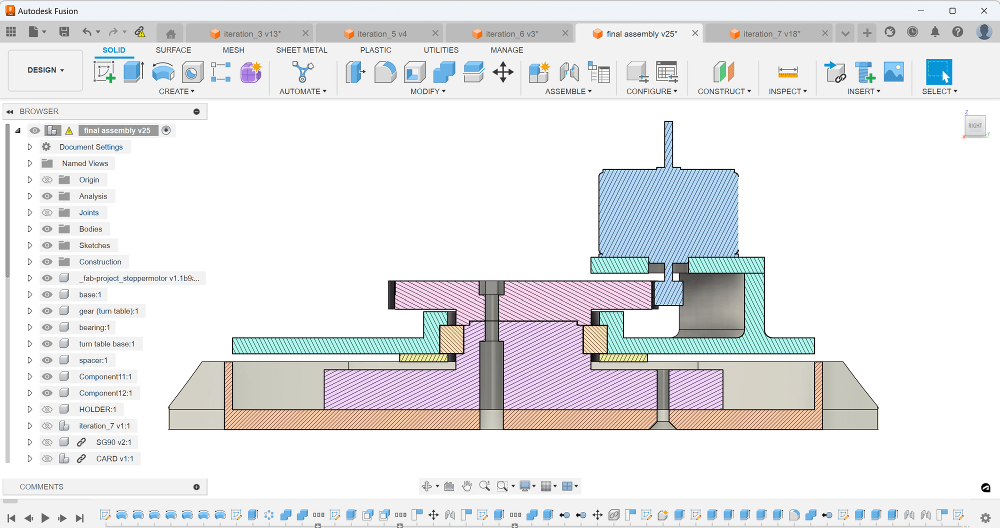
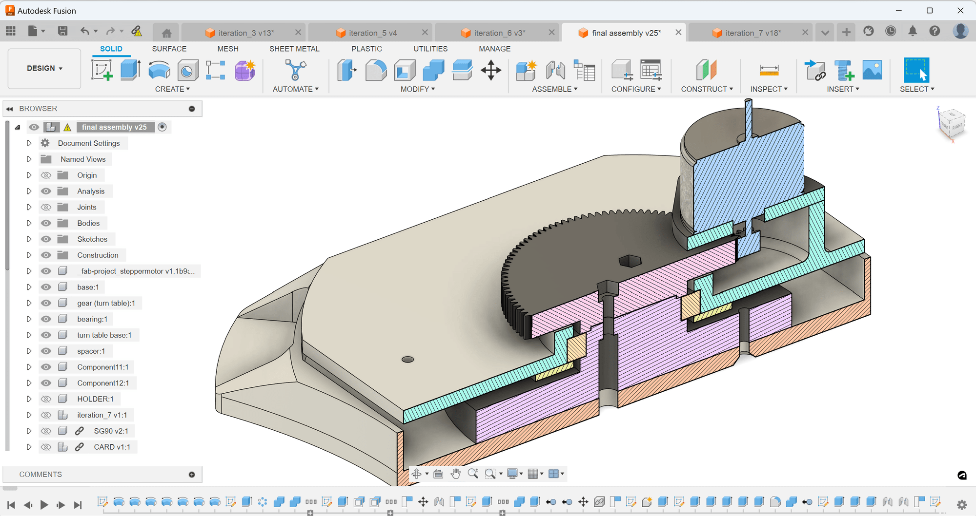
I also exported the 3D file of the PCB from KiCAD for system integration. You can see how the design looks.
Then I moved on to designing the outer case. Here you can see the enclosure I have designed for this system.
here is the design process step by step
.png)
.png)
.png)
.png)
.png)
.png)
.png)
.png)
.png)
.png)
.png)
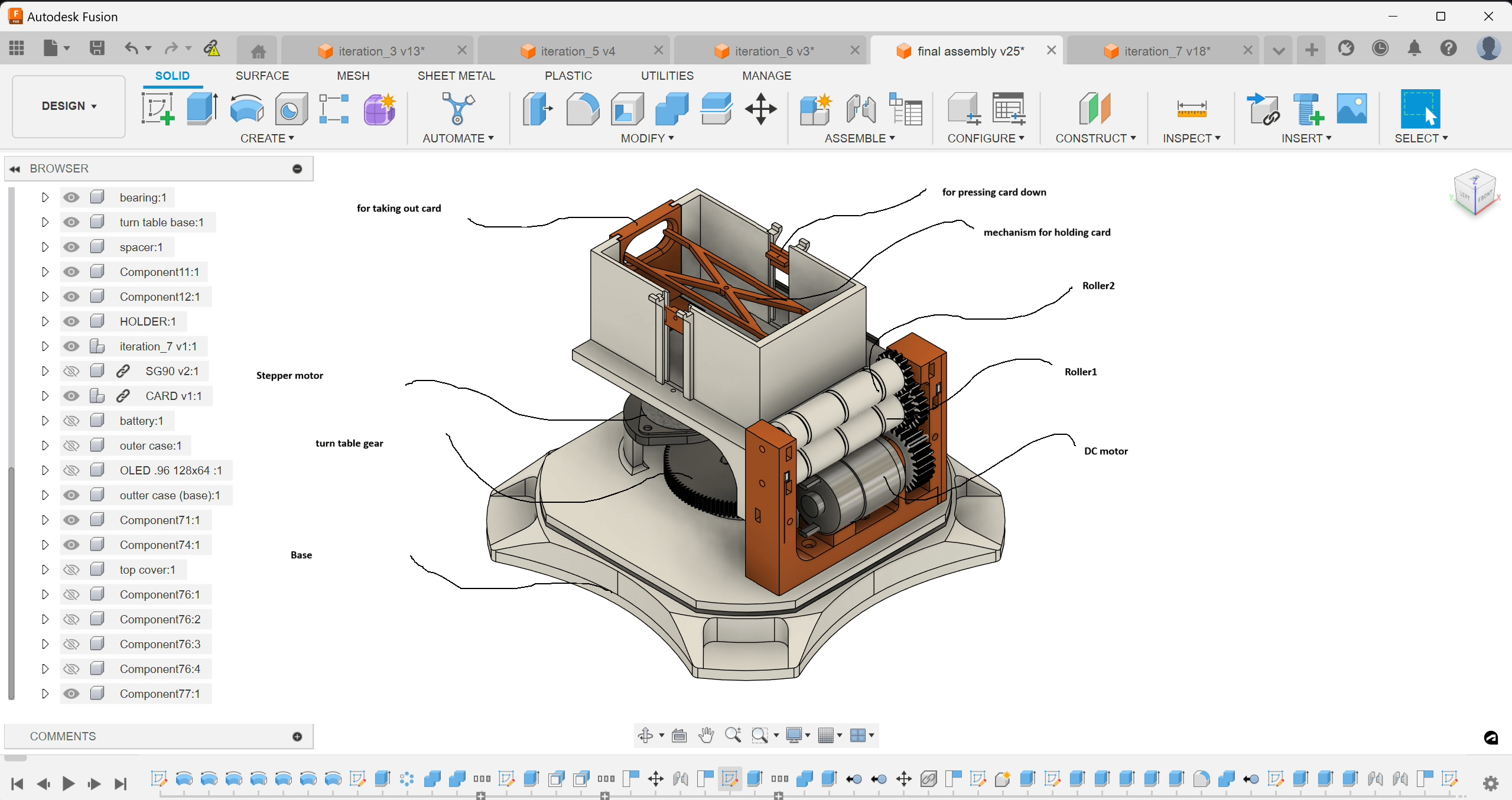
This mechanism helps the cards exert force downwards, allowing the servo to push the bottom card forward. It also facilitates retrieving the cards after distribution.
This mechanism also helps push the cards downwards.
Here is the complete design.
MANUFACTURING AND ASSEMBLY
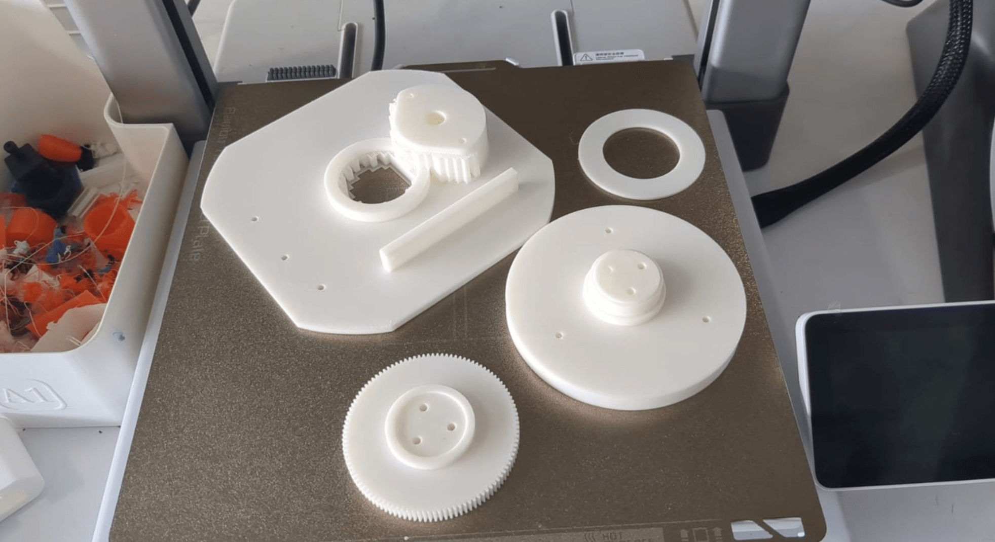
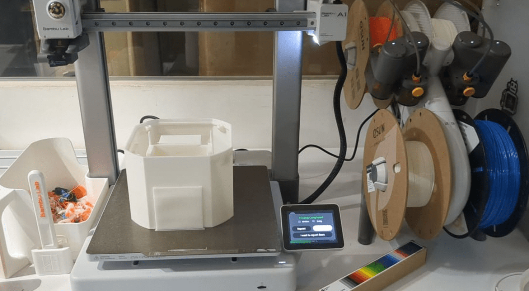
I started the fabrication process using mostly 3D-printed parts, and the top lid was laser-cut.
3d printed parts of the encloser
Laser cutting the top lid
This is how the top lid works: I have attached magnets, which help secure the attachments and make it easy to remove necessary items.
After fabricating all the parts, I assembled them together. Here is a short video showing the assembly process.
here is the short clip of the programming process . You can find the code at the bottom of this page.
Here is the result—you can see my project distributing cards.
Presentation slide